Verilog interview Questions
While both blocking and nonblocking assignments are procedural assignments, they differ in behaviour with respect to simulation and logic
synthesis as follows:

How can I model a bi-directional net with assignments influencing both source and destination?
The assign statement constitutes a continuous assignment. The changes on the RHS of the statement immediately reflect on the LHS net. However, any changes on the LHS don't get reflected on the RHS. For example, in the following statement, changes to the rhs net will update the lhs net, but not vice versa.
System Verilog has introduced a keyword alias, which can be used only on nets to have a two-way assignment. For example, in the following code, any changes to the rhs is reflected to the lh s , and vice versa.
wire rhs , lhs
assign lhs=rhs;
System Verilog has introduced a keyword alias, which can be used only on nets to have a two-way assignment. For example, in the following code, any changes to the rhs is reflected to the lh s , and vice versa.
module test ();
wire rhs,lhs;
alias lhs=rhs;
In the above example, any change to either side of the net gets reflected on the other side.
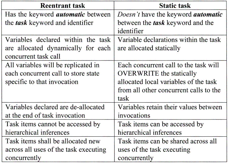
Are tasks and functions re-entrant, and how are they different from static task and function calls?
In Verilog-95, tasks and functions were not re-entrant. From Verilog version 2001 onwards, the tasks and functions are reentrant. The reentrant tasks have a keyword automatic between the keyword task and the name of the task. The presence of the keyword automatic replicates and allocates the variables within a task dynamically for each task entry during concurrent task calls, i.e., the values don’t get overwritten for each task call. Without the keyword, the variables are allocated statically, which means these variables are shared across different task calls, and can hence get overwritten by each task call.
How can I override variables in an automatic task?
By default, all variables in a module are static, i.e., these variables will be replicated for all instances of a module. However, in the case of task and function, either the task/function itself or the variables within them can be defined as static or automatic. The following explains the inferences through different combinations of the task/function and/or its variables, declared either as static or automatic:
No automatic definition of task/function or its variables This is the Verilog-1995 format, wherein the task/function and its variables were implicitly static. The variables are allocated only once. Without the mention of the automatic keyword, multiple calls to task/function will override their variables.
static task/function definition
System Verilog introduced the keyword static. When a task/function is explicitly defined as static, then its variables are allocated only once, and can be overridden. This scenario is exactly the same scenario as before.
automatic task/function definition
From Verilog-2001 onwards, and included within SystemVerilog, when the task/function is declared as automatic, its variables are also implicitly automatic. Hence, during multiple calls of the task/function, the variables are allocated each time and replicated without any overwrites.
static task/function and automatic variables
SystemVerilog also allows the use of automatic variables in a static task/function. Those without any changes to automatic variables will remain implicitly static. This will be useful in scenarios wherein the implicit static variables need to be initialised before the task call, and the automatic variables can be allocated each time.
automatic task/function and static variables
SystemVerilog also allows the use of static variables in an automatic task/function. Those without any changes to static variables will remain implicitly automatic. This will be useful in scenarios wherein the static variables need to be updated for each call, whereas the rest can be allocated each time.
What are the rules governing usage of a Verilog function?
The following rules govern the usage of a Verilog function construct:A function cannot advance simulation-time, using constructs like #, @. etc.
A function shall not have nonblocking assignments.
A function without a range defaults to a one bit reg for the return value.
It is illegal to declare another object with the same name as the function in the scope where the function is declared.
How do I prevent selected parameters of a module from being overridden during instantiation?
If a particular parameter within a module should be prevented from being overridden, then it should be declared using the localparam construct, rather than the parameter construct. The localparam construct has been introduced from Verilog-2001. Note that a localparam variable is fully identical to being defined as a parameter, too. In the following example, the localparam construct is used to specify num_bits, and hence trying to override it directly gives an error message.
Note, however, that, since the width and depth are specified using the parameter construct, they can be overridden during instantiation or using defparam, and hence will indirectly override the num_bits values. In general, localparam constructs are useful in defining new and localized identifiers whose values are derived from regular parameters.
What are the pros and cons of specifying the parameters using the defparam construct vs. specifying during instantiation?
The advantages of specifying parameters during instantiation method are:
All the values to all the parameters don’t need to be specified. Only those parameters that are assigned the new values need to be specified. The unspecified parameters will retain their default values specified within its module definition.
The order of specifying the parameter is not relevant anymore, since the parameters are directly specified and linked by their name.
The disadvantage of specifying parameter during instantiation are:
This has a lower precedence when compared to assigning using defparam.
The advantages of specifying parameter assignments using defparam are:
This method always has precedence over specifying parameters during instantiation.
All the parameter value override assignments can be grouped inside one module and together in one place, typically in the top-level testbench itself.
When multiple defparams for a single parameter are specified, the parameter takes the value of the last defparam statement encountered in the source if, and only if, the multiple defparam’s are in the same file. If there are defparam’s in different files that override the same parameter, the final value of the parameter is indeterminate.
The disadvantages of specifying parameter assignments using defparam are:
The parameter is typically specified by the scope of the hierarchies underneath which it exists. If a particular module gets ungrouped in its hierarchy, [sometimes necessary during synthesis], then the scope to specify the parameter is lost, and is unspecified. B
For example, if a module is instantiated in a simulation testbench, and its internal parameters are then overridden using hierarchical defparam constructs (For example, defparam U1.U_fifo.width = 32;). Later, when this module is synthesized, the internal hierarchy within U1 may no longer exist in the gate-level netlist, depending upon the synthesis strategy chosen. Therefore post-synthesis simulation will fail on the hierarchical defparam override.
Can there be full or partial no-connects to a multi-bit port of a module during its instantiation?
No. There cannot be full or partial no-connects to a multi-bit port of a module during instantiation
What happens to the logic after synthesis, that is driving an unconnected output port that is left open (, that is, noconnect) during its module instantiation?
An unconnected output port in simulation will drive a value, but this value does not propagate to any other logic. In synthesis, the cone of any combinatorial logic that drives the unconnected output will get optimized away during boundary optimisation, that is, optimization by synthesis tools across hierarchical boundaries.
How is the connectivity established in Verilog when connecting wires of different widths?
When connecting wires or ports of different widths, the connections are right-justified, that is, the rightmost bit on the RHS gets connected to the rightmost bit of the LHS and so on, until the MSB of either of the net is reached.
Can I use a Verilog function to define the width of a multi-bit port, wire, or reg type?
The width elements of ports, wire or reg declarations require a constant in both MSB and LSB. Before Verilog 2001, it is a syntax error to specify a function call to evaluate the value of these widths. For example, the following code is erroneous before Verilog 2001 version. reg [ port1(val1:vla2) : port2 (val3:val4)] reg1;
In the above example, get_high and get_low are both function calls of evaluating a constant result for MSB and LSB respectively. However, Verilog-2001 allows the use of a function call to evaluate the MSB or LSB of a width declaration
What is the implication of a combinatorial feedback loops in design testability?
The presence of feedback loops should be avoided at any stage of the design, by periodically checking for it, using the lint or synthesis tools. The presence of the feedback loop causes races and hazards in the design, and 104 RTL Designleads to unpredictable logic behavior. Since the loops are delay-dependent, they cannot be tested with any ATPG algorithm. Hence, combinatorial loops should be avoided in the logic.
What are the various methods to contain power during RTL coding?
Any switching activity in a CMOS circuit creates a momentary current flow from VDD to GND during logic transition, when both N and P type transistors are ON, and, hence, increases power consumption. The most common storage element in the designs being the synchronous FF, its output can change whenever its data input toggles, and the clock triggers. Hence, if these two elements can be asserted in a controlled fashion, so that the data is presented to the D input of the FF only when required, and the clock is also triggered only when required, then it will reduce the switching activity, and, automatically the power.
The following bullets summarize a few mechanisms to reduce the power consumption:
How do I model Analog and Mixed-Signal blocks in Verilog?
First, this is a big area.Analog and Mixed-Signal designers use tools like Spice to fully characterize and model their designs.My only involvement with Mixed-Signal blocks has been to utilize behavioral models of things like PLLs, A/Ds, D/As within a larger SoC.There are some specific Verilog tricks to this which is what this FAQ is about (I do not wish to trivialize true Mixed-Signal methodology, but us chip-level folks need to know this trick).
A mixed-signal behavioral model might model the digital and analog input/output behavior of, for example, a D/A (Digital to Analog Converter).So, digital input in and analog voltage out.Things to model might be the timing (say, the D/A utilizes an internal Success Approximation algorithm), output range based on power supply voltages, voltage biases, etc.A behavioral model may not have any knowledge of the physical layout and therefore may not offer any fidelity whatsoever in terms of noise, interface, cross-talk, etc.A model might be parameterized given a specific characterization for a block.Be very careful about the assumptions and limitations of the model!
Issue #1; how do we model analog voltages in Verilog.Answer: use the Verilog real data type, declare “analog wires” as wire[63:0] in order to use a 64-bit floating-type represenation, and use the built-in PLI functions:
$rtoi converts reals to integers w/truncation e.g. 123.45 -> 123
$itor converts integers to reals e.g. 123 -> 123.0
$realtobits converts reals to 64-bit vector
$bitstoreal converts bit pattern to real
That was a lot.This is a trick to be used in vanilla Verilog.The 64-bit wire is simply a ways to actually interface to the ports of the mixed-signal block.In other words, our example D/A module may have an output called AOUT which is a voltage.Verilog does not allow us to declare an output port of type REAL.So, instead declare AOUT like this:
module dtoa (clk, reset..... aout.....);
....
wire [63:0]aout;// Analog output
....
We use 64 bits because we can use floating-point numbers to represent out voltage output (e.g. 1.22x10⁻³ for 1.22 millivolts).The floating-point value is relevant only to Verilog and your workstation and processor, and the IEEE floating-point format has NOTHING to do with the D/A implementation.Note the disconnect in terms of the netlist itself.The physical “netlist” that you might see in GDS may have a single metal interconnect that is AOUT, and obviously NOT 64 metal wires.Again, this is a trick.The 64-bit bus is only for wiring.You may have to do some quick netlist substitutions when you hand off a netlist.
In Verilog, the real data type is basically a floating-point number (e.g. like double in C).If you want to model an analog value either within the mixed-signal behavorial model, or externally in the system testbench (e.g. the sensor or actuator), use the real data type.You can convert back and forth between real and your wire [63:0] using the PLI functions listed above.A trivial D/A model could simply take the digital input value, convert it to real, scale it according to some #defines, and output the value on AOUT as the 64-bit “psuedo-analog” value.Your testbench can then do the reverse and print out the value, or whatever.More sophisticated models can model the Successive Approximation algorithm, employ look-ups, equations, etc. etc.
That’s it.If you are getting a mixed-signal block from a vendor, then you may also receive (or you should ask for) the behavioral Verilog models for the IP.
How do I synthesize Verilog into gates with Synopsys?
The answer can, of course, occupy several lifetimes to completely answer.. BUT.. a straight-forward Verilog module can be very easily synthesized using Design Compiler (e.g. dc_shell). Most ASIC projects will create very elaborate synthesis scripts, CSH scripts, Makefiles, etc. This is all important in order automate the process and generalize the synthesis methodology for an ASIC project or an organization. BUT don't let this stop you from creating your own simple dc_shell experiments!
Let's say you create a Verilog module named foo.v that has a single clock input named 'clk'. You want to synthesize it so that you know it is synthesizable, know how big it is, how fast it is, etc. etc. Try this:
target_library = { CORELIB.db } <--- This part you need to get from your vendor...
read -format verilog foo.v
create_clock -name clk -period 37.0
set_clock_skew -uncertainty 0.4 clk
set_input_delay 1.0 -clock clk all_inputs() - clk - reset
set_output_delay 1.0 -clock clk all_outputs()
compile
report_area
report_timing
write -format db -hierarchy -output foo.db
write -format verilog -hierarchy -output foo.vg
quit
You can enter all this in interactively, or put it into a file called 'synth_foo.scr' and then enter:
dc_shell -f synth_foo.scr
You can spend your life learning more and more Synopsys and synthesis-related commands and techniques, but don't be afraid to begin using these simple commands.How can I pass parameters to my simulation?
A testbench and simulation will likely need many different parameters and settings for different sorts of tests and conditions. It is definitely a good idea to concentrate on a single testbench file that is parameterized, rather than create a dozen seperate, yet nearly identical, testbenches. Here are 3 common techniques:
· Use a define. This is almost exactly the same approach as the #define and -D compiler arg that C programs use. In your Verilog code, use a `define to define the variable condition and then use the Verilog preprocessor directives like `ifdef. Use the '+define+' Verilog command line option. For example:
... to run the simulation ..
verilog testbench.v cpu.v +define+USEWCSDF
... in your code ...
`ifdef USEWCSDF
initial $sdf_annotate (testbench.cpu, "cpuwc.sdf");
`endif
The +define+ can also be filled in from your Makefile invocation, which in turn, can be finally
filled in the your UNIX promp command line.
Defines are a blunt weapon because they are very global and you can only do so much with
them since they are a pre-processor trick. Consider the next approach before resorting to
defines.
· Use parameters and parameter definition modules. Parameters are not preprocessor definitions and they have scope (e.g. parameters are associated with specific modules). Parameters are therefore more clean, and if you are in the habit of using a lot of defines; consider switching to parameters. As an example, lets say we have a test (e.g. test12) which needs many parameters to have particular settings. In your code, you might have this sort of stuff:
module testbench_uart1 (....)
parameter BAUDRATE = 9600;
...
if (BAUDRATE > 9600) begin
... E.g. use the parameter in your code like you might any general variable
... BAUDRATE is completely local to this module and this instance. You might
... have the same parameters in 3 other UART instances and they'd all be different
... values...
Now, your test12 has all kinds of settings required for it. Let's define a special module
called testparams which specifies all these settings. It will itself be a module instantiated
under the testbench:
module testparams;
defparam testbench.cpu.uart1.BAUDRATE = 19200;
defparam testbench.cpu.uart2.BAUDRATE = 9600;
defparam testbench.cpu.uart3.BAUDRATE = 9600;
defparam testbench.clockrate CLOCKRATE = 200; // Period in ns.
... etc ...
endmodule
The above module always has the same module name, but you would have many different
filenames; one for each test. So, the above would be kept in test12_params.v. Your
Makefile includes the appropriate params file given the desired make target. (BTW: You
may run across this sort of technique by ASIC vendors who might have a module containing
parameters for a memory model, or you might see this used to collect together a large
number of system calls that turn off timing or warnings on particular troublesome nets, etc.
etc.)
· Use memory blocks. Not as common a technique, but something to consider. Since Verilog has a very convenient syntax for declaring and loading memories, you can store your input data in a hex file and use $readmemh to read all the data in at once.
In your testbench:
module testbench;
...
reg [31:0] control[0:1023];
...
initial $readmemh ("control.hex", control);
...
endmodule
You could vary the filename using the previous techniques. The control.hex file is just a file
of hex values for the parameters. Luckily, $readmemh allows embedded comments, so you
can keep the file very readable:
A000 // Starting address to put boot code in
10 // Activate all ten input pulse sources
... etc...
Obviously, you are limitied to actual hex values with this approach. Note, of course, that
you are free to mix and match all of these techniques
No comments:
Post a Comment